GAP / FLUSH · GEOMETRY · VALIDATION
18 min readOne algorithm is not enough.
A deep look at why complex laser profiles need morphology-aware geometry, explicit failure logic and validation evidence—not just a function that returns two numbers.
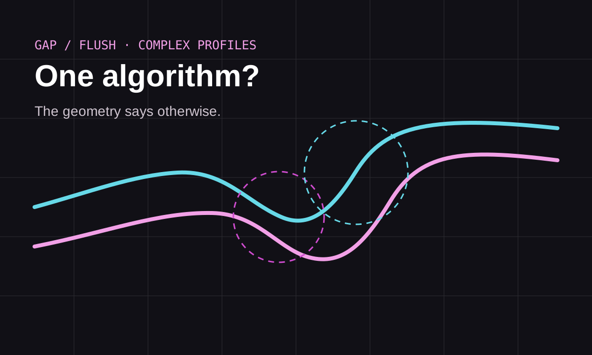
In dimensional inspection, the most dangerous algorithm is not always the one that crashes. It is the one that returns a plausible value from the wrong geometric construction. GAP and FLUSH make this problem especially visible because two profiles can look broadly similar while demanding different definitions of edge, reference direction, tangent, normal, arc or transition point.
1. The measurement is a geometry problem before it is a coding problem
A laser line profiler gives a sampled profile, often represented as points (xᵢ, zᵢ). That point cloud is not yet a GAP or FLUSH measurement. The software still has to decide which portions of the profile represent surfaces, rounded edges, transitions and reference geometry.
For a line–line interface, a surface normal may be a natural direction. For opposing rounded hems, a circle-centre or radial construction may be more meaningful. For an arc–line morphology, blindly applying a circle–circle method can produce a numerically stable but physically wrong result.
2. Segmentation is part of the test basis
It is tempting to treat segmentation as preprocessing and only validate the final algorithm. That is a mistake. If the selected line, arc or transition point is wrong, every downstream result is contaminated.
| Layer | What must be checked | Typical failure |
|---|---|---|
| Profile | orientation, scale, missing points, outliers | mirrored or truncated geometry |
| Segmentation | surface/arc boundaries, transition points | edge assigned to the wrong primitive |
| Geometry | line, circle, tangent, normal, radial vector | valid fit on the wrong region |
| Measurement | reference side, direction and intersection | correct math, wrong definition |
| Evidence | plots, logs, residuals, rejection reason | unexplainable pass/fail |
3. Morphology-aware algorithms
A robust library should not pretend that every profile belongs to one universal model. Instead, each method should define a validity envelope. Example families include line–line, circle–circle, arc–line and arc–edge constructions. The algorithm registry can then associate each method with minimum geometry requirements and explicit failure messages.
method = choose_method(profile_morphology)

requirements = method.required_geometry()
if not segmentation.satisfies(requirements):
    return Failure("required geometry unavailable")

result = method.execute(segmentation)
return validate_construction(result)
This is much better than silently refitting geometry until something works. A measurement system should distinguish “no valid construction” from “valid construction with value X”.
4. Transition points are not decorative
For complex automotive profiles, a transition point often anchors the change from an approximately linear surface to a curved edge. Moving this point by a few samples can change the fitted primitive, local normal, circle centre and therefore the final projection direction. That makes transition-point sensitivity a useful validation dimension.
5. A good algorithm has a failure taxonomy
“Algorithm failed” is not useful enough. During development, failure reasons should be structured so patterns can be analysed across datasets.
- Segmentation failure: required primitive or transition cannot be identified.
- Geometric degeneracy: nearly parallel lines, unstable circle fit, invalid intersection.
- Domain failure: morphology does not match the method’s assumptions.
- Numerical failure: singular solve, NaN, overflow or tolerance issue.
- Plausibility failure: result exists but violates physical or engineering bounds.
6. Validation means more than comparing one “expected value”
For an engineering algorithm, I would separate validation evidence into four levels:
- Geometric correctness: construction is visually and mathematically defensible.
- Dataset consistency: behaviour remains stable across representative profile families.
- Reference comparison: output is compared with trusted data or accepted methods when available.
- Robustness: controlled perturbations do not create discontinuous or unreasonable results.
That is why a desktop platform such as GAPFLUSH Studio is valuable during development: it makes the intermediate evidence inspectable instead of reducing the workflow to a CSV full of final numbers.
7. Measurement uncertainty still matters
An algorithm can be perfectly deterministic and still operate on uncertain measurements. Instrument resolution, calibration, operator positioning, segmentation and model choice all contribute to the final measurement quality. The G3F research literature explicitly treats repeatability, reproducibility and processing strategy as part of the measurement-system problem rather than isolated software concerns.
The exact combination depends on the measurement model and correlation between terms, but the principle is important: algorithm validation sits inside metrology, not outside it.
8. What I would put in a regression suite
- Representative profiles for every supported morphology.
- Known difficult profiles with ambiguous transitions.
- Profiles where each algorithm must intentionally reject the input.
- Boundary cases near geometric thresholds.
- Orientation/reversal cases.
- Numerical stability checks and tolerance-based comparisons.
- Saved plots or geometric evidence for selected golden profiles.
9. The real goal: explainable measurement logic
The point is not to create the largest possible collection of algorithms. It is to create a controlled set of methods whose assumptions are visible, whose inputs are traceable and whose results can be defended. In industrial validation, “why this value?” matters almost as much as the value itself.
10. Engineering acceptance should include the construction, not only the number
A powerful pattern is to define acceptance on multiple outputs: the numerical GAP/FLUSH result, the chosen primitives, the transition points, residuals and the method status. This prevents a plausible number from hiding an invalid geometric path.
assert result.status == "valid"
assert result.method in allowed_methods
assert result.geometry.transition_left is not None
assert result.geometry.transition_right is not None
assert result.metrics.residual_rms < residual_limit
assert abs(result.value - reference.value) <= tolerance
11. Dataset design matters as much as algorithm design
A useful validation dataset should be stratified by morphology, acquisition quality and expected difficulty. Easy repeated profiles can make a method look robust while hiding failure on mixed arc-line, weak-transition or partially observed geometries. I prefer keeping a small golden set for regression plus a broader exploratory set for failure discovery.